

Custom Pick and Place Vision System: What Information Should You Give the Integrator?
Providing Production-Grade Part Samples and Material Variances
Supplying physical part samples from real production lots is the most critical information handoff in any vision project. Integrators cannot reliably calibrate optical edge detection algorithms using clean, 3D-printed prototype components or sterile CAD models. Real-world injection molding, metal stamping, and die-casting processes produce subtle material variations that profoundly affect machine vision reliability.
Buyers should provide a comprehensive sample set representing complete production variances: - Multiple production lots: Supply parts manufactured across different raw material batches to account for resin color shifts and pigment density variations. - Multi-cavity tooling samples: Include components molded from different mold cavities, as minor parting line flash and gate vestige heights alter part silhouettes. - Surface finish and coating variances: Provide parts with actual post-processing finishes, including matte sandblasting, reflective plating, anodizing, or residual stamping oils. - Out-of-spec boundary parts: Supply known defective components with maximum allowable burrs, minor dents, or slight warping to validate defect filtering thresholds.
Testing vision algorithms against real physical samples allows integrators to engineer illumination and optical filtering that accommodate natural process drift without generating false rejects.
Defining Field of View, Resolution, and Inspection Accuracy
Accurate vision specification requires defining the relationship between the physical inspection area, camera sensor resolution, and required placement tolerance. Machine vision integrators need clear dimensional boundaries to select appropriate optical sensors and lenses.
Critical optical parameters to define include: - Field of view dimensions: Specify the exact physical area the camera must cover, such as a 200 mm by 200 mm flexible feeder vibration plate or an indexing conveyor nest. - Working distance: State available vertical clearance between the camera lens and the component surface, factoring in robot arm travel paths and overhead frame beams. - Required inspection accuracy: Define whether the system needs general positional guidance (±0.1 mm) or high-precision feature verification (±0.01 mm to ±0.05 mm). - Sensor resolution and lens selection: High-resolution sensors between five and twelve megapixels paired with low-distortion telecentric lenses eliminate optical parallax errors across the field of view.
Clarifying these optical requirements ensures the Custom Pick and Place Vision System delivers sub-pixel edge detection without optical distortion across the entire working zone.
Optical Illumination Geometry and Wavelength Selection
Proper lighting geometry separates readable part contours from confusing background noise. Integrators must know the optical reflectivity, surface texture, and color of incoming parts to design an effective illumination configuration.
Engineers should discuss several lighting configurations with the integrator: - Transmitted backlighting: Mounting high-uniformity LED backlight plates beneath translucent feeder trays produces sharp black silhouettes, ideal for verifying outer geometric profiles and pin pitch. - Polarized coaxial illumination: Directing light along the camera optical axis through polarizing filters eliminates specular reflections on shiny metallic terminals and polished electronics shielding cans. - Diffuse dome lighting: Spherical diffuse domes eliminate harsh shadows on complex three-dimensional stamped parts, providing uniform illumination across curved surfaces. - Wavelength selection: Selecting specific LED wavelengths, such as red, blue, or infrared, enhances optical contrast against colored plastics or suppresses ambient factory daylight variations.
Specifying part optical characteristics early allows integrators to build robust lighting enclosures that isolate the vision system from ambient factory lighting fluctuations.
Cycle Time Budgets and Processing Latency Limits
High-speed automated cells require vision systems that process images rapidly without stalling robotic motion. A high-speed robotic arm capable of seventy picks per minute sits idle if the vision computer takes too long to analyze part contours.
Project teams must allocate explicit time budgets across the vision sequence: - Image acquisition and strobe exposure: Typically allocated two to five milliseconds to capture sharp images on briefly paused feeder surfaces. - Contour extraction and pattern matching: Allocated fifteen to twenty milliseconds to locate multiple part candidates in the field of view. - Coordinate transformation and communication output: Allocated five milliseconds to transmit calibrated X-Y coordinates and rotational angles to the robot motion controller. - Total processing latency budget: The entire vision cycle must complete within 20 to 30 milliseconds to match high-speed robotic cycle times.
Establishing an explicit latency ceiling ensures the Custom Pick and Place Vision System utilizes multi-threaded software algorithms capable of sustaining high-volume production throughput.
Coordinate Hand-Eye Calibration and Communication Protocols
Translating camera pixels into accurate physical coordinates requires systematic hand-eye calibration between the vision camera and the robotic manipulator. Integrators must understand the physical mounting relationship and network communication protocols used in the cell.
Key integration parameters to specify include: - Camera mounting geometry: State whether the primary camera is mounted statically to an overhead frame or mounted on the robot wrist, and whether secondary in-flight cameras are required. - Calibration grid procedures: Establish calibration protocols utilizing precision dot grid plates to calculate pixel-to-millimeter scaling, optical distortion correction, and rotational offsets. - Industrial fieldbus interfaces: Define network communication protocols, such as Ethernet TCP/IP sockets, EtherCAT, PROFINET, or RS232 serial links. - Data packet structuring: Standardize coordinate string formatting, delimiter characters, and handshake acknowledgement bits between the vision computer and the PLC.
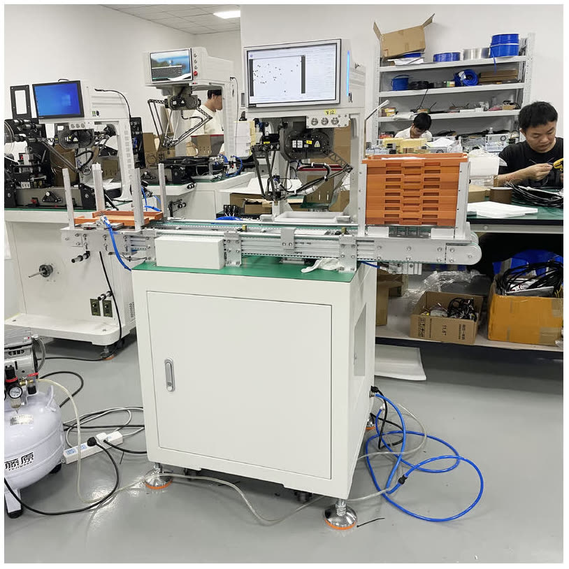
Automation manufacturers like FIDER standardize coordinate hand-eye calibration protocols to ensure plug-and-play communication between intelligent vision systems and Delta robotics, achieving repeatable placement accuracy of ±0.05 mm.
Defect Filtering Criteria and False Rejection Limits
A pick-and-place vision system often serves as both a motion guide and a quality inspection gate. Clarifying the boundary between positional guidance and defect detection prevents operational conflicts on the plant floor.
Essential defect criteria to define include: - Defect inspection scope: Clearly delineate whether the camera should only verify part pickability or also inspect micro-scratches, burrs, flashing, or color variations. - Quantitative acceptance thresholds: Define numerical tolerances for acceptable dimensional drift rather than subjective descriptions like clean or smooth. - Maximum acceptable false rejection rate: Establish realistic limits, such as false reject rates below 0.1%, to prevent unnecessary component scrap. - Reject handling procedures: Specify whether rejected parts should be picked and diverted to a quarantine bin or left on the feeder for secondary inspection cycles.
Providing comprehensive technical details to your Custom Pick and Place Vision System integrator ensures rapid commissioning and reliable production throughput. To review vision system specifications or discuss optical integration requirements for delicate components, explore engineering resources at https://www.fdrautomation.com/ to schedule an integration consultation.
FIDER
FIDER
Legal Disclaimer:
EIN Presswire provides this news content "as is" without warranty of any kind. We do not accept any responsibility or liability for the accuracy, content, images, videos, licenses, completeness, legality, or reliability of the information contained in this article. If you have any complaints or copyright issues related to this article, kindly contact the author above.
